- 您现在的位置:买卖IC网 > Sheet目录341 > MAX8647ETE+T (Maxim Integrated)IC LED DRVR WT/RGB BCKLGT 16TQFN
Ultra-Efficient Charge Pumps for
Six White/RGB LEDs in 3mm x 3mm Thin QFN
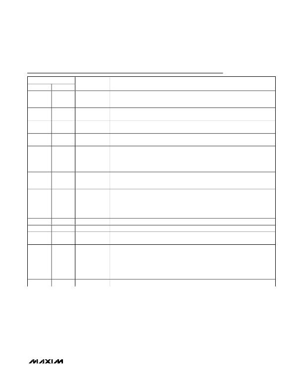
Pin Description
PIN
MAX8647 MAX8648
NAME
FUNCTION
Supply Voltage Input. The input voltage range is 2.7V to 5.5V. Bypass IN to GND with a
1
1
IN
1μF ceramic capacitor as close as possible to the IC. IN is high impedance during
shutdown. Connect IN to the anodes of all the LEDs.
2
3
4
5
6
2
3
4
5
6
GND
C1P
C2P
C2N
C1N
Ground. Connect GND to system ground and the input bypass capacitor as close as
possible to the IC.
Transfer Capacitor 1 Positive Connection. Connect a 1μF ceramic capacitor from C1P
to C1N.
Transfer Capacitor 2 Positive Connection. Connect a 1μF ceramic capacitor from C2P
to C2N.
Transfer Capacitor 2 Negative Connection. Connect a 1μF ceramic capacitor from C2P
to C2N. An internal 10k Ω resistor pulls C2N to GND during shutdown.
Transfer Capacitor 1 Negative Connection. Connect a 1μF ceramic capacitor from C1P
to C1N.
Charge-Pump Negative Output. Connect a 1μF ceramic capacitor from NEG to GND. In
7
7
NEG
shutdown, an internal 10k Ω resistor pulls NEG to GND. Connect the exposed paddle to
NEG directly under the IC.
LED Current Regulators. Current flowing into LED_ is based on the internal registers.
Connect LED_ to the cathodes of the external LEDs. LED_ is high impedance during
8–13
8–13
LED6–LED1
shutdown. For the MAX8647, program any unused LED_ to off and LED_ can be
shorted to ground or left unconnected. For the MAX8648, short any unused LED_ to IN
prior to power-up to disable the corresponding current regulator.
14
15
16
—
—
—
SDA
SCL
V DD
I 2 C Data Input. Data is read on the rising edge of SCL.
I 2 C Clock Input. Data is read on the rising edge of SCL.
Logic-Input Supply Voltage. Connect to the supply voltage driving SDA and SCL.
Bypass V DD to GND with a 0.1μF ceramic capacitor.
Enable and Serial-Pulse Dimming Control. ENA controls LED1, LED2, and LED3. ENB
controls LED4 and LED5. ENC controls LED6. Drive EN_ logic-high to turn on the IC
—
14, 15, 16
ENC, ENB, ENA
and enable the corresponding LED_ at 24mA each. Drive an individual EN_ logic-low
for greater than 4ms to turn off the corresponding-current regulators or drive all three
EN_ low to place the IC in shutdown. See the Serial-Pulse Dimming Control (MAX8648)
section.
—
—
EP
Exposed Paddle. Connect to NEG.
_______________________________________________________________________________________
7
发布紧急采购,3分钟左右您将得到回复。
相关PDF资料
MAX8702ETP+
IC DRVR MOSFET DUAL 20-TQFN
MAX8790AETP+T
IC LED DRVR WHITE BCKLGT 20-TQFN
MAX8790ETP+T
IC LED DRVR WHITE BCKLGT 20-TQFN
MAX8791GTA+
IC MOSFET DRIVER 8-TQFN
MAX8811EEE+
IC DRVR DL PHASE HS 16-QSOP
MAX8821ETI+
IC LED DRVR WHITE BCKLGT 28-TQFN
MAX8822ETE+T
IC LED DRVR WHITE BCKLGT 16-TQFN
MAX8830EWE+T
IC LED DRVR WHITE BCKLGT 16-UCSP
相关代理商/技术参数
MAX8648ETE
制造商:MAXIM 功能描述:Pb Free
MAX8648ETE+
功能描述:LED照明驱动器 Charge Pump for 6 White/RGB LEDs RoHS:否 制造商:STMicroelectronics 输入电压:11.5 V to 23 V 工作频率: 最大电源电流:1.7 mA 输出电流: 最大工作温度: 安装风格:SMD/SMT 封装 / 箱体:SO-16N
MAX8648ETE+T
功能描述:LED照明驱动器 Charge Pump for 6 White/RGB LEDs RoHS:否 制造商:STMicroelectronics 输入电压:11.5 V to 23 V 工作频率: 最大电源电流:1.7 mA 输出电流: 最大工作温度: 安装风格:SMD/SMT 封装 / 箱体:SO-16N
MAX8648EVKIT+
制造商:Maxim Integrated Products 功能描述:MAX8648 EVAL KIT - Rail/Tube
MAX8649AEWE+T
功能描述:直流/直流开关调节器 1.8A Step-Down Regulator RoHS:否 制造商:International Rectifier 最大输入电压:21 V 开关频率:1.5 MHz 输出电压:0.5 V to 0.86 V 输出电流:4 A 输出端数量: 最大工作温度: 安装风格:SMD/SMT 封装 / 箱体:PQFN 4 x 5
MAX8649BEWE+T
功能描述:直流/直流开关调节器 1.8A Step-Down Regulator RoHS:否 制造商:International Rectifier 最大输入电压:21 V 开关频率:1.5 MHz 输出电压:0.5 V to 0.86 V 输出电流:4 A 输出端数量: 最大工作温度: 安装风格:SMD/SMT 封装 / 箱体:PQFN 4 x 5
MAX8649EVKIT+
制造商:Maxim Integrated Products 功能描述:1.8A STEP-DOWN REGULATOR W/DIFFERENTIAL REMOTE SENSE IN 2MM - Boxed Product (Development Kits)
MAX8649EWE+
制造商:Maxim Integrated Products 功能描述:1.8A STEP-DOWN REGULATOR W/DIFFEREN - Rail/Tube
